You are here: Home • PRODUCT • LED street Lighting
Categories:LED street Lighting
Introduce: Features ■Universal input voltage design(90Vac~305Vac) ■Output voltage and current parameters support the client settings ■High power factor, low harmonics ■High efficiency design (up to 90%) ■Protection Design: Short-circuit, over-voltage, over-temperature ■suitable for LED Lighting ■IP65/IP67 grade,could be install in indoor and outdoor ■3 years warranty Dimming 3 in1 online ...
Features
■Universal input voltage design(90Vac~305Vac)
■Output voltage and current parameters support the client settings
■High power factor, low harmonics
■High efficiency design (up to 90%)
■Protection Design: Short-circuit, over-voltage, over-temperature
■suitable for LED Lighting
■IP65/IP67 grade,could be install in indoor and outdoor
■3 years warranty
Dimming
3 in1 online dimming(Equipped with 3-in-1 dimming function, through the product dimming cable access resistance / PWM signal / (0 ~ 10Vdc) level of any signal, to achieve online dimming function) Programming (output current control settings, up to 2 dimming section)
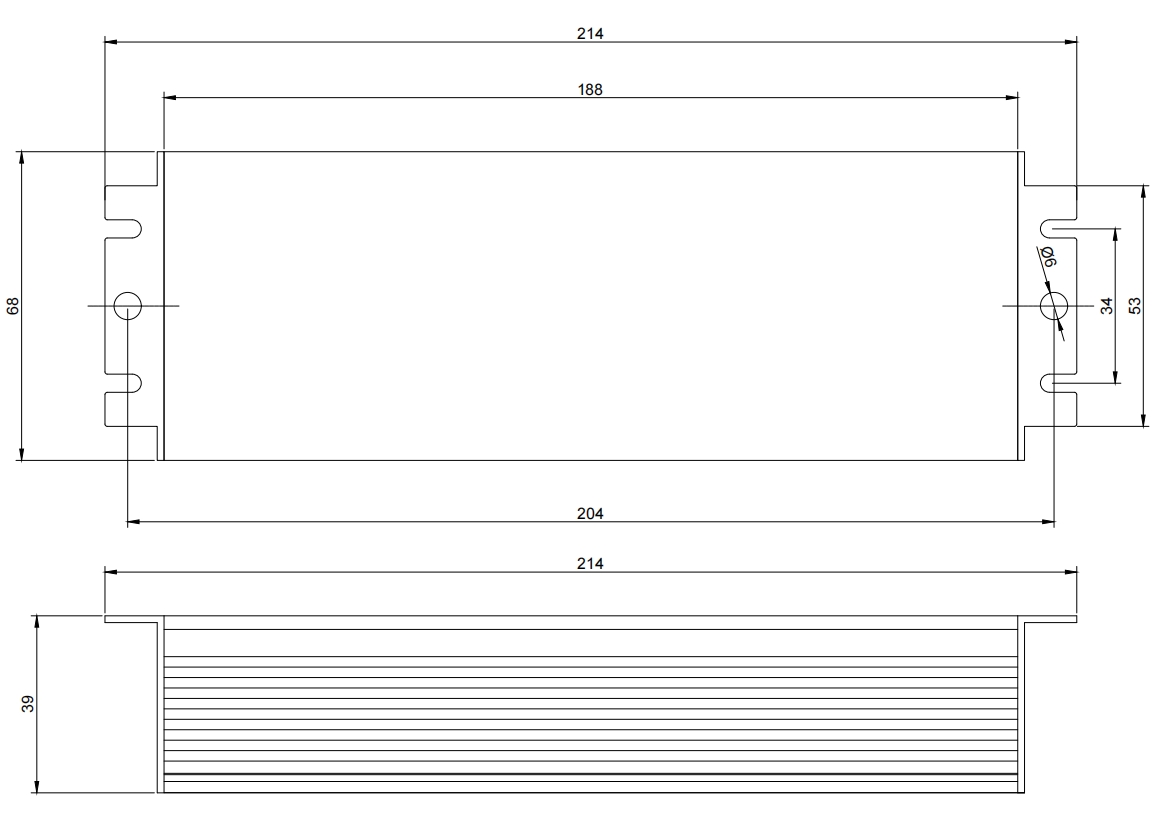
Structure
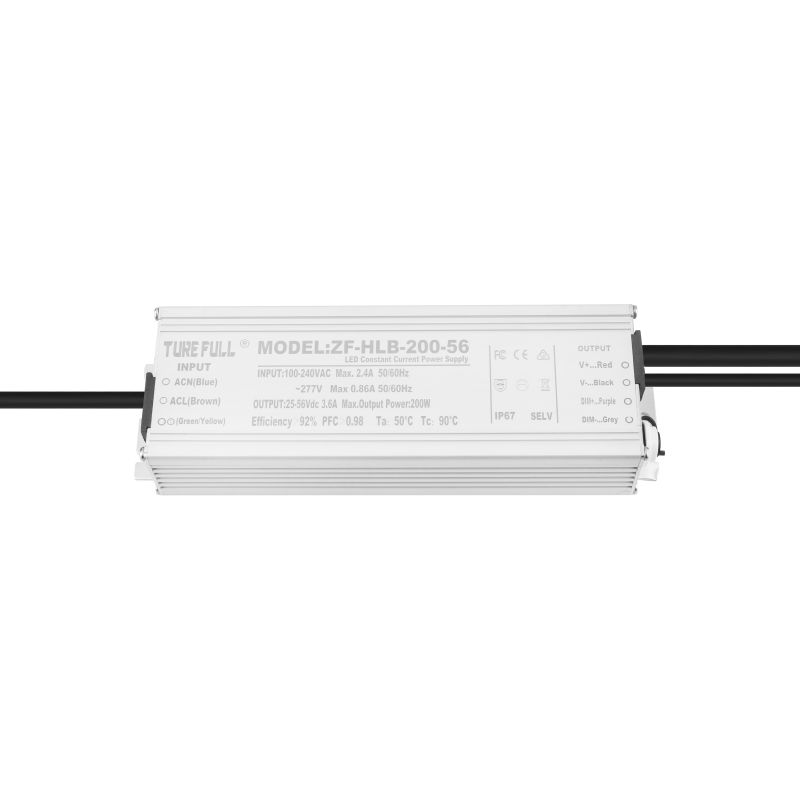
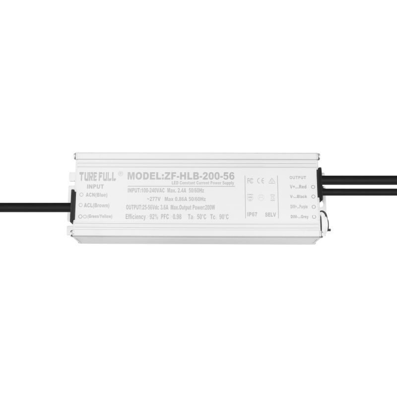
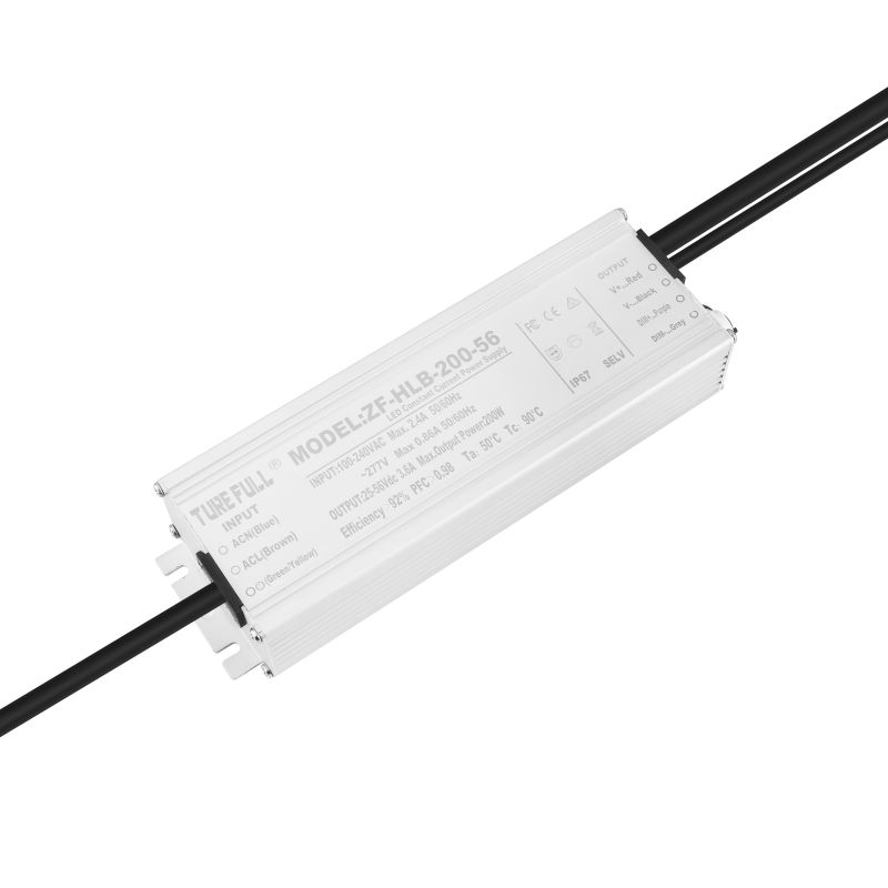
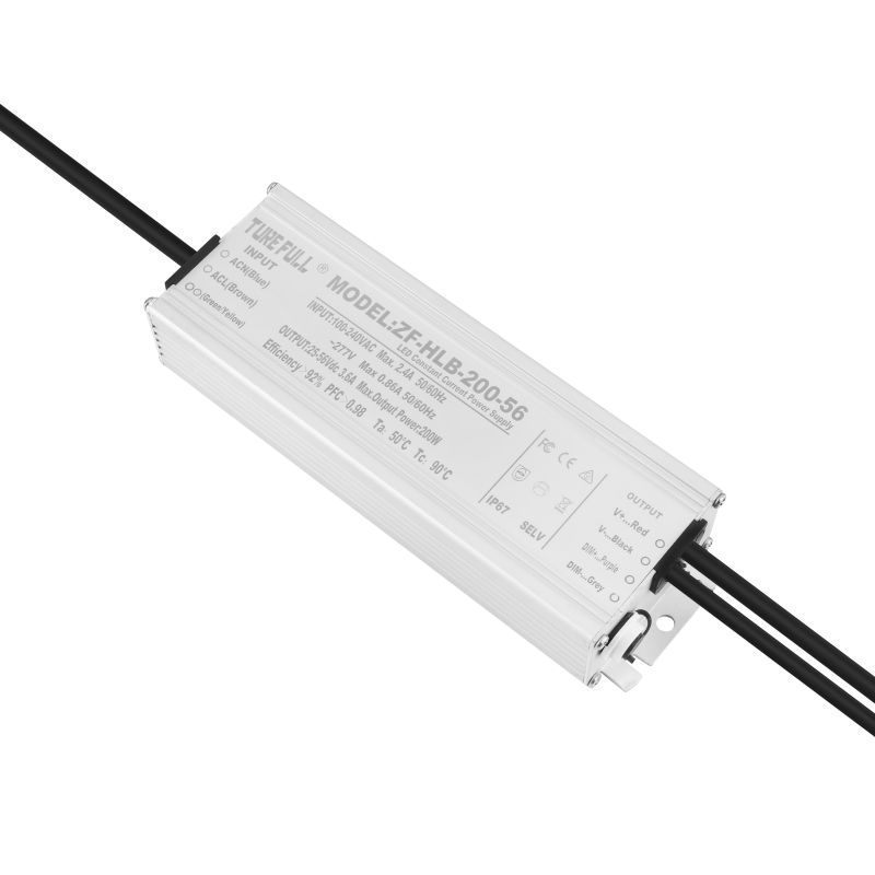
L*W*H:L188*W68*H39mm
Specification
| Modeld | ZF-HLB-200-36 | ZF-HLB-200-42 | ZF-HLB-200-48 | ZF-HLB-200-54 | Customized | |
| Output | No-load voltage(MAX) | 37VDC | 43VDC | 49VDC | 55VDC | Customized |
| Output current(Typ) | 5.5A | 4.75A | 4.16A | 3.7A | Customized | |
| Output Power(MAX) | 203W | 203W | 203W | 203W | 203W | |
| Ripple and noise Remarks2 | 300mV | 300mV | 300mV | 300mV | 300mV | |
| Output voltage range | 25-36VDC | 25-42VDC | 25-48VDC | 38-54VDC | Customized | |
| Conversion efficiency(Typ) | ≥86% | ≥86% | ≥87% | ≥88% | ≥88% | |
| Current error(MAX) | ±2% | ±2% | ±2% | ±2% | ±2% | |
| Linear adjustment rate | ±2% | ±2% | ±2% | ±2% | ±2% | |
| Load Regulation | ±2% | ±2% | ±2% | ±2% | ±2% | |
| Start Time Remarks3 | ≤800ms,≤1500ms(Full load)230VAC/115AC | |||||
| Hold time(Typ) | 10msFull load 230VAC/115VAC | |||||
| Input | Voltage range | 100-300VAC Or 130-430VDC(When the AC input voltage is higher than 277VAC, the APFC is turned off and the power supply works without PFC correction.) | ||||
| Frequency Range | 47-63HZ | |||||
| Power factor(Typ) | PF≥0.98 230VACFull load | |||||
| Total harmonic distortion(Typ) | <15%(Loaded lamps as standard) | |||||
| Alternating current(Typ) | <0.8A/115VAC, <0.45A/230VAC, <0.35A/277VAC | |||||
| Inrush current(Typ) | Cold start<80A /230VAC | |||||
| Leakage current | <0.75MA/300VAC | |||||
| Protection | Overcurrent | 100% | ||||
| Short circuit | Protection mode: snoring, the short circuit can be restored after removal | |||||
| Overload protection | Maximum operating voltage limit。 | |||||
| Over temperature protection | Product internal temperature monitoring point>Start after 90 °C, reduce the output current as the temperature rises (the dimming product does not have this function) | |||||
| Environment | Operating temperature | -40---+60℃ | ||||
| Working humidity | 20-95%RH,No condensation | |||||
| Storage temperature, humidity | -40-+80℃,20-95%RH | |||||
| Maximum temperature rise | +30℃ Windless open environment, maximum temperature point of the enclosure | |||||
| Vibration resistant | 10-500HZ,5G 12Minute/cycle,X, Y, Z axis 72 minutes each | |||||
| Safety and electromagnetic compatibility | Safety regulations Remarks4 | EN 61347-1:2008+A1:2011+A2:2013 , EN 61347-2-13:2006 , EN 62493:2010 | ||||
| Withstand voltage | I/P-O/P:3.75KVAC I/P-FG:2KVAC O/P-FG:1KVAC | |||||
| Insulation resistance | I/P-O/P, I/P-FG, O/P-FG: 100M Ohms/500VDC/25℃/70%RH | |||||
| Electromagnetic compatibility emission | EN55015 , EN55022(CISPR22),Class B,EN61000-3-2 :2006+AA:2009 | |||||
| Electromagnetic compatibility immunity | EN55024-A , EN61000-3-3:2013 | |||||
| Lightning surge | Common mode | L/N-FG,±6KV | ||||
| Differential mode | L-N,±5KV | |||||
| Wire | Rubber line | Input line3*0.75² | ||||
| Rubber line | Output line2*0.75² | |||||
| Shell | All aluminum Shell | Silicone filling and filling | ||||
| Other | MTBF | ≥150Khrs;MIL-HDBK-217F(25℃) | ||||
| Body size | L208*W68*H39mm | |||||
| Product Weight | ||||||
| Package carton size | L188*W75*H43 | |||||
| Remarks |
1.Unless otherwise stated, all specifications are measured at an input temperature of 230VAC. 25°C ambient temperature. 2.Ripple and noise measurement method: use a 0.52mm twisted pair cable, and the terminal should be connected with 0.1uf and 47uf capacitors in parallel and measure at 20MHz bandwidth. 3.The startup time is measured under the cold start, and frequent switching machines may change the startup time. 4.Safety designTUVEN61347-1,EN61347-2-13,IEC/EN60968-1.2004+A1:2006 5.The power supply is considered to be a component used in conjunction with the terminal equipment. Because the EMC is affected by the complete unit, the terminal equipment manufacturer needs to confirm the EMC of the entire unit. |
|||||
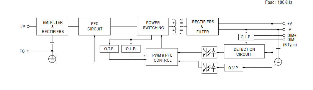
Block diagram
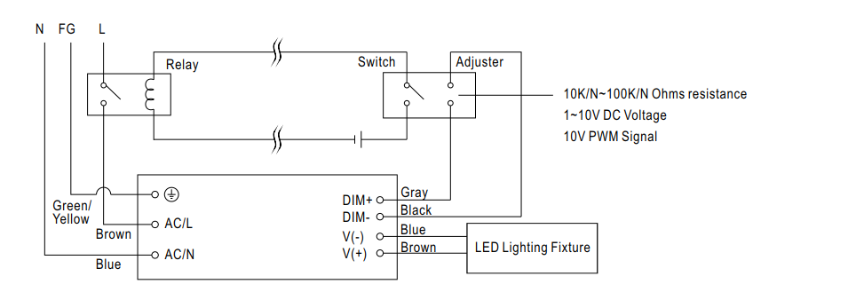
Dimming function (optional)
※ The output current can be adjusted by potentiometer with DIM+, DIM-connected 1~10Vdc, 10V PWM signal, and maximum resistance of 100K.
※ When using the potentiometer to control the dimming, only one product can be controlled. If you need to control multiple products, you need to change the maximum value of the potentiometer. The resistance change calculation formula is: 100K/parallel control product = demand resistance The use of potentiometer to control multiple products is also affected by other conditions, and the actual experience is poor, so it is not recommended to use potentiometer to control multiple products.)
※ When controlling 10 products with 1~10Vdc, 10V PWM signal, ensure that the controller output current is ≥3mA
※ After the product is powered on, the DIM+ output line cannot be short-circuited with the LED+ output line to prevent the high voltage of the LED+ output from damaging the constant current control system inside the product.
※ Adjust the reference resistance of the output current (typical)
| Resistance Value | 10KΩ | 20KΩ | 30KΩ | 40KΩ | 50KΩ | 60KΩ | 70KΩ | 80KΩ | 90KΩ | 100KΩ | OPEN |
| Rated current percentage | 10% | 20% | 30% | 40% | 50% | 60% | 70% | 80% | 90% | 100% | 95%-108% |
※1-10V Dimming Function Adjusts Output Current (Typical)
| Voltage adjustment | 1V | 2V | 3V | 4V | 5V | 6V | 7V | 8V | 9V | 10V | OPEN |
| Rated current percentage | 10% | 20% | 30% | 40% | 50% | 60% | 70% | 80% | 90% | 100% | 95%-108% |
※10V PWM Signal Adjust Output Current Value (Typical) Frequency Range: 100Hz-3KHz
| Duty Ration | 10% | 20% | 30% | 40% | 50% | 60% | 70% | 80% | 90% | 100% | OPEN |
| Rated current percentage | 10% | 20% | 30% | 40% | 50% | 60% | 70% | 80% | 90% | 100% | 95%-108% |
Dimming connection block diagram of lighting device using controller to turn on/off
2. Dimming method 2: timing dimming
Timer dimming internally uses a microcontroller as a timer. A dimming ratio of 5% to 100% can be achieved.
This dimming method uses the power-on time as 0 o'clock. When the power supply starts the timer, it will restart at 0:00:00:00. Once the power is turned off or the power-on time is lost, the time will start again.
The minimum current changes by 1%. The maximum current changes by 95%. The minimum time set value is 1 second, and the maximum time setting value is infinite.
For example, the output power of the customer is reduced to 70% after 3 hours of start-up, 50% after 5 hours, 35% after 6.5 hours, and then maintained. This can be achieved by this function.
Note: The start time of the dimming and the percentage of the dimming output current are set by the customer and cannot be changed once shipped.
This control mode cannot turn off the power.
There are two ways of current regulation, one is real-time, and the other is gradual, such as reducing the weight to 100% and reducing it to 50%. In real time, it only takes 1 second to reduce the current by 100% to 50%. The gradual change is a gradual decrease at a rate of 1% per second. The reduction from 100% to 50% takes 50 seconds to complete. . Customers can choose a suitable change in a more practical environment.
Declaration
1.the picture is for reference only, products in kind prevail.
2.Due to errors in the test equipment, the conversion efficiency is only for reference.
3.power can not be soaked in water for a long time.
Product Usage Notes
1. When the device is powered, please pay attention to the correct installation of the input and output terminals.
2. When the power supply is turned on for the first time, if a light flash occurs, check the DC output terminal; if it is confirmed that the load voltage of the DC output terminal is lower than the minimum operating voltage, when the load voltage is lower than the minimum operating voltage, the power supply is not in operation. In the normal work area, various abnormal conditions will occur.
3. When the power is turned on for the first time, if the load power is low, check the DC output voltage and confirm whether the DC output voltage is lower than the maximum operating voltage. If the load voltage is higher than or equal to the maximum operating voltage, When the power supply enters the constant voltage operation mode, the power supply loses the constant current function and changes to the load impedance constant current. After encountering this situation, it is necessary to replace the power supply with higher operating voltage to properly match the lamps.
Warranty instructions
1.the warranty date start date is the product date of manufacture
2.The product damage caused by using the environment beyond the nominal range of the specification is not covered by the warranty.
3.Product damage caused by incorrect installation and use is not covered by the warranty.
4. Product failure caused by long-term immersion in water is not covered by the warranty.
5.Users will not warranty after disassembling the product